Visualizing element fields using lines and cylinders
Lines and cylinders are graphical representations which can be used to visualize 1-D elements in CMGUI - line elements at the edges of 2-D faces or 3-D elements. In general, lines or cylinders are used to visualize the basic shape of a mesh. When you load a mesh (exnode and exelem files) into CMGUI, the mesh is by default represented by lines of the default colour and thickness: white lines 1 pixel thick. This means that a lines graphic is created in the default scene (see the scene editor), with the default settings (Figure 1).
If you wish to create these lines in the graphics window, use the go to the file menu in CMGUI and select Read, then Node file. Read in cube.exnode from the example a2 directory. Then using the Read and Elements file menu options, read in cube.exelem from the same directory. If you now create a graphics window (using the Graphics menu item 3-D window) you will see this cube rendered in 1 pixel thick white lines.
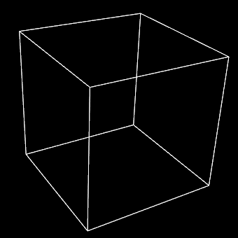
Figure 1: The default graphical setting lines created for a cube mesh. This mesh was created by reading the cube.exnode and cube.exelem files from example a2. Note that the example a2 com file creates cylinders to visualize the cube mesh.
Settings for lines
Two default scene settings are important for lines and cylinders. In the scene editor, the selected tessellation controls the number of line segments used to draw each line. The Circle discretization value is used to control how many sides are used to draw each cylinder. Higher numbers will give "rounder" looking cylinders (Figure 2).
Lines have relatively few settings for altering their appearance (Figure 2). The following settings are available for lines:
- Coordinate field: When you check this box, you are able to select the coordinate field that the lines are drawn according to. This is used any time the coordinate field used for the lines needs to differ from the default coordinate field used for the whole graphical element (in the general settings).
- Exterior: When this check box is selected, the lines will only be drawn on the exterior faces of a 3D mesh, or the outside edges of a 2D mesh. This can be useful with large, complex meshes.
- Face: Checking this box allows you to select which face of 3D elements is visualized by lines. Faces are selected according to one of the 3 xi directions of the element, and it's value (either 0 or 1).
- Select mode: This drop-down menu allows you to select different selection behaviours for the lines.
- select_on - The default setting; line elements are able to be selected and selected elements are highlighted by rendering in the selected material.
- no_select - No selection or highlighting of line elements.
- draw_selected - only selected lines are drawn.
- draw_unselected - only unselected lines are drawn.
- Material: This drop down menu allows you to select which material the lines will be rendered as. Materials are defined in the material editor window. Note: the material for lines is unshaded. This means that lines only use the diffuse colour for the selected material to draw the lines.
- Width: You can enter a value in this box to set the thickness of the lines in pixels. This width is independent of zoom, and remains constant through any transformation. Setting this value to 0 results in lines of 1 pixel wide (the default).
- Data: This setting allows you to choose a field which is used to colour the lines according to a spectrum. Use the Spectrum drop-down menu to choose from one of the spectra defined in the spectrum editor window.
- Selected material: Use this drop-down menu to select which material will be used to render selected lines.
In addition to these settings there is a command line setting that can be very useful when using line based visualizations: gfx modify window 1 set perturb_lines. This command helps to prevent the "dotted lines" effect that occurs when lines and surfaces interfere.
Note: if no lines appear, you may not have added faces (and lines) to the mesh - try the gfx define faces command.
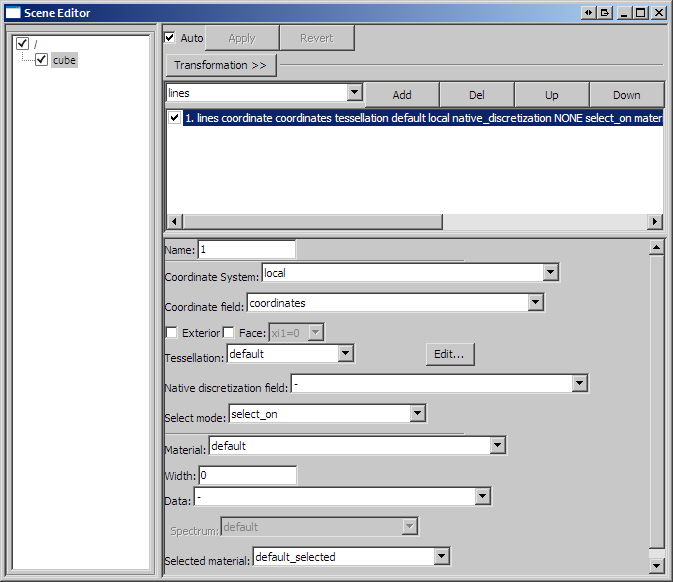
Figure 2: The scene editor settings available for a lines graphical setting.
Settings for cylinders
Cylinders are very similar to lines, with a few additional parameters. A cylinders graphical setting will draw cylinders along all the same elements that a lines graphical setting would. Cylinders are different to lines in that they have a size relative to the mesh - therefore they scale with zooming just like other objects that have an actual "size" in the scene. The number of "faces" that are used to display cylinders is set under the General settings under Circle dicretization. The higher the number, the more circular the cylinders will appear. The default setting is for six sides. Cylinders have the following settings in addition to those for lines:
- Constant radius: This is the radius of the cylinders, in the same units as the coordinate system.
- Scalar radius: This drop-down menu allows you to select a field to scale the radius of the cylinders. A good example of this is shown in example a4.
- Scale factors This box allows you to enter three values as factors for the scaling in three dimensions. It is possible using this to exaggerate or reduce the scaling, or to restrict scaling to one or two dimensions.